TC Rotary Knob with slider Sensor
A rotary knob utilizing capacitive sensing to detect the movement of an indexed ring is suggested. Consumers are interested in a knob with an integrated user interface.


Technischer Lösungsvorschlag A2015-009
Unternehmenseinheit: Diehl AKO Stiftung & Co. KG
Description:
A rotary knob utilizing capacitive sensing to detect the movement of an indexed ring is suggested.
Consumers are interested in a knob with an integrated user interface. Preferably this knob shall be rotating. Further a knob with metal look and feel is preferred, as it gives a worthy appearance.
This invention offers a large rotary knob with display elements in the centre and thesensing movement of the rotary knob made of metal. The suggested system is completely sealed and water proof. Sensing of the rotary movement is realized by a cylindrical small angle capacitive sensor. For sensing minimal sensors, one or two, are used as opposed to an array of sensors. Capacitive sensing of the rotating index requires the sensor to be a cylinder or arc.
Until now sensing the movement of a metal ring has been done by using of optical sensors. Another method uses mechanical pots connected to the ring by a gear(s). Capacitive sensing methods have been proposed by: Using an array of sensors placed under the knob and a single index. Depositing and array of sensors around the inside cylinder of the frame is quite expensive.
The suggested system is cheaper and simpler than optical, mechanical and capacitive array systems. The optical and capacitive array systems can be sealed with difficulty, but the mechanical cannot. The capacitive array, although very similar, is difficult to implement, because of the cost and complexity of depositing the many sensors on the inside of a cylinder.
This invention senses the movement of a metal ring rotating around a display knob by use of a capacitive slider sensor. This is done by placing a circular array of indexes around the metal ring in combination with a cylindrical arc capacitive slider sensor. This creates a system where the metal indexes are always parallel to the sensor. This system can be used in large rings and the system can be completely sealed and are waterproof. The innovative item of this invention is the use of a capacitive slider sensor in sensing the movement of a cylinder and the method of creating a cylinder arc capacitive sensor.
Further characteristics and advantages of the invention will become apparent from the following description, which is given in examples of specific non-limiting embodiments, with reference to the accompanying drawings, in which:
- Fig. 1 shows an exploded view of a metal knob with capacitive sensing,
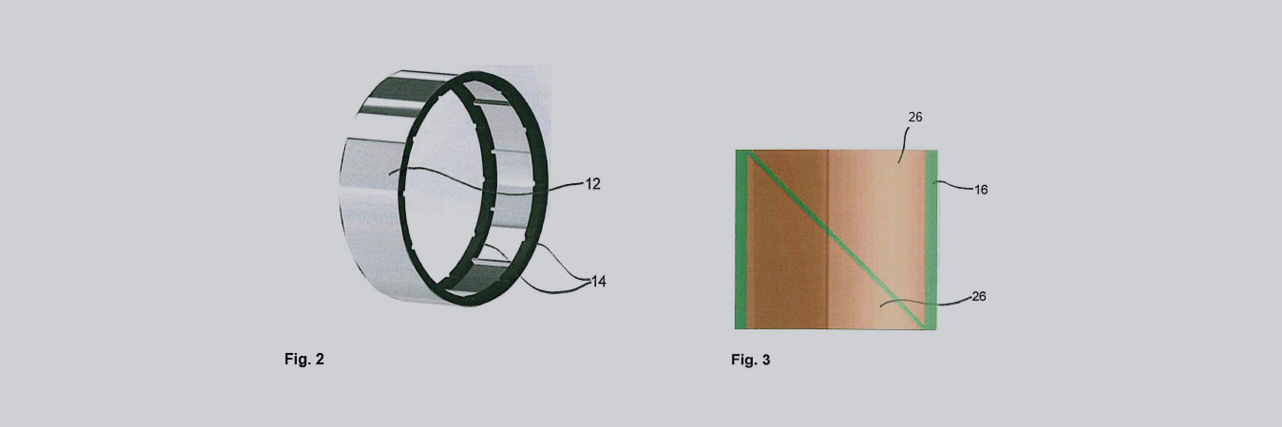
- Fig. 2 shows a metal ring with guide rings,
- Fig. 3 shows a capacitive sensing being accomplished by two triangular sensors,
- Fig. 4 shows the sensor signals of the two triangular sensors while the extrusions pass over the sensors, and
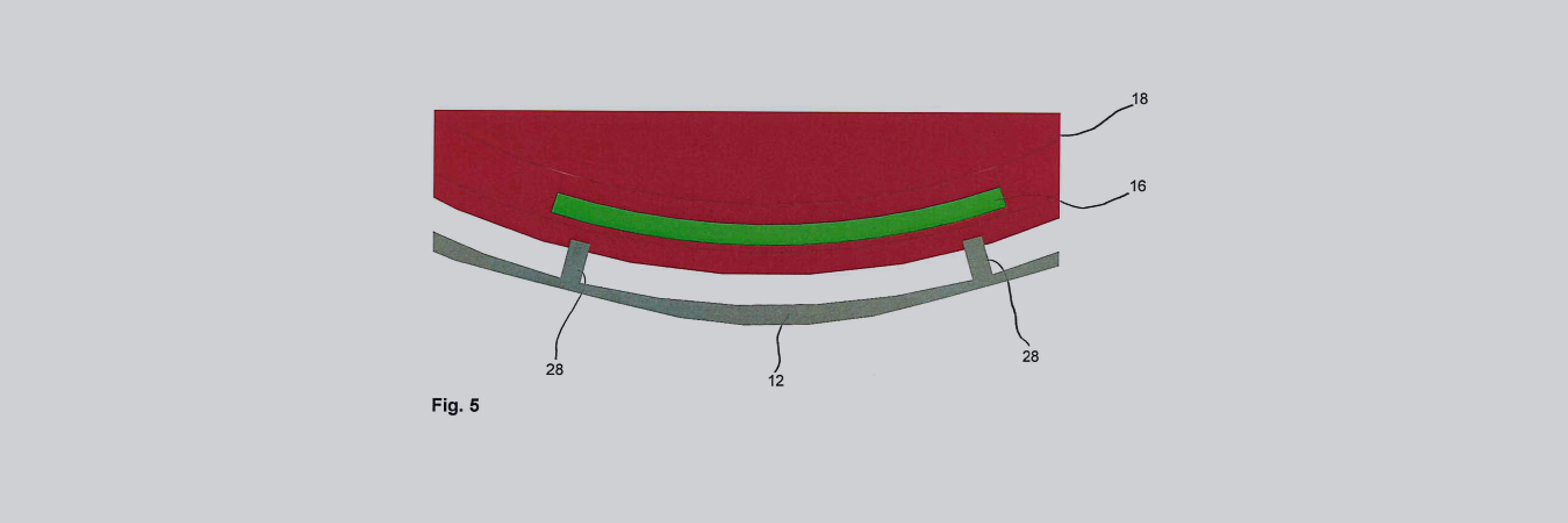
- Fig. 5 shows the PCB parallel to the metal ring with two extrusions.
In Fig. 1 the components of a metal knob 8 with capacitive sensing are shown, namely a base 10, an extruded metal ring 12 with two guide rings 14, a capacitive sensing PCB 16 to be inserted in the frame 18 with ball dents 20, a TFT display 22 and a lens 24. In this example the components are fixed by screws 30.
The design shown in Fig. 2 is an 80mm knob 8. The system has only three moving parts. The metal ring 12 and two plastic guide rings 14. The guide rings 14 centre up the metal ring 12 and act as bearings. If necessary, low friction plastic could be used for a smoother feel when turning. Indents in the plastic rings 14 along with the ball dents 20 provide the haptic feedback. These can be tuned for number of stops and feel.
The metal ring 12 could be made of stainless steel. Such a ring has a superior look and feel compared to plastic. More over this it is possible to produce rings with large dimensions.
However, there are many advantages to using extruded aluminum:
- No limitation to only round knobs.
- Complex geometries such as adding finger indents are possible.
- Existing extruded aluminum heatsink suppliers can produce cheaply.
- Many different finishes are possible, including anodized colors.
- Small extrusions evenly spaced around the interior are sensed by the capacitive system.
The capacitive sensing is accomplished by one or two triangular sensors 26 (Fig. 3). Which are sensing extrusions 28 in the metal ring 12. These are spaced 30° apart in the design shown. As the ring 12 rotates the extrusions 28 pass over the sensors 26. As shown in Fig. 4, one sensor 26 will see an increasing signal while the other will see a decreasing signal. With this system we can detect:
- Direction
- Speed
- Relative position within the angle.
- Whether there is a hand on the knob (proximity detection).
The sensors 26 must be close to parallel with the metal indexes 28 in order to work properly. This is why a curved PCB 16 must be used. The capacitive sensing of the ring 12 offers the possibility of sensing the direction of ring movement and the relative position of the ring 12.
We suggest a standard PCB 16 instead of a flexible one. There are several advantages of the small angle sensing:
- A small standard PCB can be used.
- There is no need for a flexible PCB to be wrapped all the way around the knob, or other more complex geometries.
- The PCB can be press fit and eliminate the need for fasteners.
- This is done be creating a pocket in the frame, and using a ~0.5mm PCB.
- The PCB is forced to bow when inserted in the pocket.
- The force of the PCB trying to straighten itself locks it in the pocket.
- This has the added advantage of keeping the sensors and metal extrusions in parallel (see Fig. 5).
There are many display options due to the large hollow in the centre of the knob 8 and the sealed nature of the design. Complex displays 22 are possible because of the large space in the knob 8 and behind the front of the knob 8, respectively. The centre could be filled with electronics and display, or with many light-guides and LEDs.
The design shown is configured with an off the shelf 2.4” TFT display 22. Size limit on the TFT display 22 is about 5mm less than the diameter of the knob 8.
The front lens 24 can be configured with any combination of capacitive touch buttons and/or screen. The touch buttons can be configured into the front lens 24. The design shown in Fig. 1 uses the lens 24, along with four screws 30, to hold the system together. However, the lens 24 can be glued to the front to avoid this.
The plastic guide rings 14 give many possible options for haptic feed back. Such as:
- Ball dent
- Plastic spring
- Delta spring
The current design uses a ball dent 20 system, configured with one on either side of the ring 12. This is highly customizable with both the feel and number of positions being configurable. E.g. by changing the number and strength of the ball dents 20.
The force used to turn the ring 12, i.e. the amount of friction, can also be tuned. Although it is not yet clear weather low friction plastic will need to be used.