Impact fuse for a projectile
This invention describes animpact detonator with improved reliability and reduced dud rate compared to prior art detonators.


TECHNICAL SOLUTION PROPOSAL J2023-001
Business Unit: JUNGHANS Microtec GmbH
Description:
The proposed technical solution deals with an impact fuze for a projectile. Such impact igniters are known from the prior art, such as DE 10 2008 053 990 B4. These have an outer housing, for example, in which the actual ignition device with its individual ignition components is located. The ignition device usually comprises an ignition chain, which in its firing position comprises two or more ignition charges arranged one behind the other. In its securing position, the ignition chain of the ignition device can be interrupted by an interrupter which removes the interruption between the ignition charges when unlocked, for example delayed by an escapement with armature and armature wheel, so that a detonator that can be pierced via a detonator needle located in the area of the igniter tip can be ignited by a subsequent ignition charge when the igniter hits the target. The subsequent ignition charge can be arranged in the interrupter or in a carrier element arranged below the interrupter. The interrupter and/or carrier element can be locked in position by one or more bolts and can be released, for example, electronically or due to inertia as a result of the firing acceleration.
Task
The task of the proposed technical solution is to create an improved impact fuze which does not detonate even if the impact fuze mounted or unmounted on the projectile falls unintentionally or during a planned drop test and an associated impact and/or which nevertheless ensures reliable triggering if the impact fuze strikes a target at an angle.
Solution
The proposed technical solution suggests providing a support element in a free space between a lateral outer wall of the housing of a fuse unit and an inner wall of an outer housing of the detonator, in which the housing of the fuse unit is arranged. The housing of the fuse unit comprises detonator components such as detonator and fuse elements, in particular, for example, bolts, interrupters, escapement, carrier element, etc.
The support element is skilfully designed in such a way that it at least partially embraces the lateral outer wall of the housing of the security unit in the manner of a sleeve and has one or more laterally projecting areas which are designed in such a way that they bridge a lateral free space between the inner wall of the outer housing and the lateral outer wall of the housing of the security unit, in that the inner wall of the outer housing of the security unit which are designed in such a way that they bridge a lateral free space between the inner wall of the outer housing and the lateral outer wall of the housing of the security unit, in that the inner wall of the outer housing and the lateral outer wall of the housing of the security unit are connected to one another via the projecting area or areas - or in other words: The projecting area or areas provide support for the fuse unit housing relative to the outer housing of the detonator by being in contact with the inner wall of the outer housing of the detonator.
The proposed solution is based on the realisation that the components of an ignition device, which are sensitive to an impact on a target, for example, are protected to a certain extent against deformation and thus damage from an impact igniter:
- on the one hand through the outer housing of the detonator and the housing of the fuse unit and
- on the other hand by the free space provided a) between the opposing components of the detonator, namely the cover plate of the fuse unit housing facing the detonator tip and the firing needle carrier with firing needle, which still allows the detonator to be pierced by the firing needle through the opening in the cover plate opposite the detonator even if the impact on a target is tilted relative to the longitudinal axis of the detonator, and/or b) in the area between the inner area of the outer housing of the detonator and the area of the housing of the fuse unit.
Furthermore, the proposed solution is based on the consideration that, despite this free space provided to protect against deformation of the outer housing, an unimpaired functional sequence, i.e. reliable firing, in particular in the event of an impact on a target at a shallow angle, is not necessarily guaranteed: This is because, particularly in the event of severe deformation of the outer housing, the deformation of the outer housing may propagate to the housing of the fuse unit despite the free space, in that the deformed inner wall of the outer housing presses on the outer wall of the housing of the fuse unit and may also deform it. also deforms it. This can cause components of the fuse unit to shift due to their mass, which can result in damage to the components and impair the operation of the impact igniter.
The proposed solution recognises that by providing such a support element in this free space, the housing of the fuse unit and thus its components are supported against the outer housing of the detonator at an angle on the side opposite the target contact in the event of a target impact. The projecting area or areas of the support element are practically designed to give way in the area of the deformation of the outer housing. A crumple zone is preferably formed, which reduces damage to the housing of the fuse unit and its components.
As a result of the introduction of a support element in accordance with the proposed solution, the reliability of the impact detonator is increased and the dud rate is reduced:
No or at least only minor damage to components of the safety device occurs during drop tests. In the case of a target impact at a flat impact angle, a displacement of the defined positions of the detonator / piercing primer and the ignition needle intended for the piercing can be avoided - and thus a miss of the piercing primer. With the "self-disassembly" detonator function, in which the piercing detonator is moved against the ignition needle, the support element ensures that the positions of the piercing detonator and ignition needle are aligned with each other and centred as far as possible..
In one embodiment, the support element can be designed as a sleeve with a projecting area in the form of a circumferential flange at one end of the sleeve. The flange can be provided with recesses, for example in the form of incisions, in order to improve the formation of a crumple zone. The sleeve can also be made of a harder material, e.g. metal, especially if a flange with recesses is provided.
In one embodiment, the support element embraces the cover plate of the fuse unit facing the firing pin. When the support element is designed as a sleeve with a projecting area, the inner wall / inner diameter of the sleeve and the outer wall / outer diameter of the cover plate are matched to each other in such a way that the sleeve can be pushed onto the cover plate so that it engages around it.
Design examples
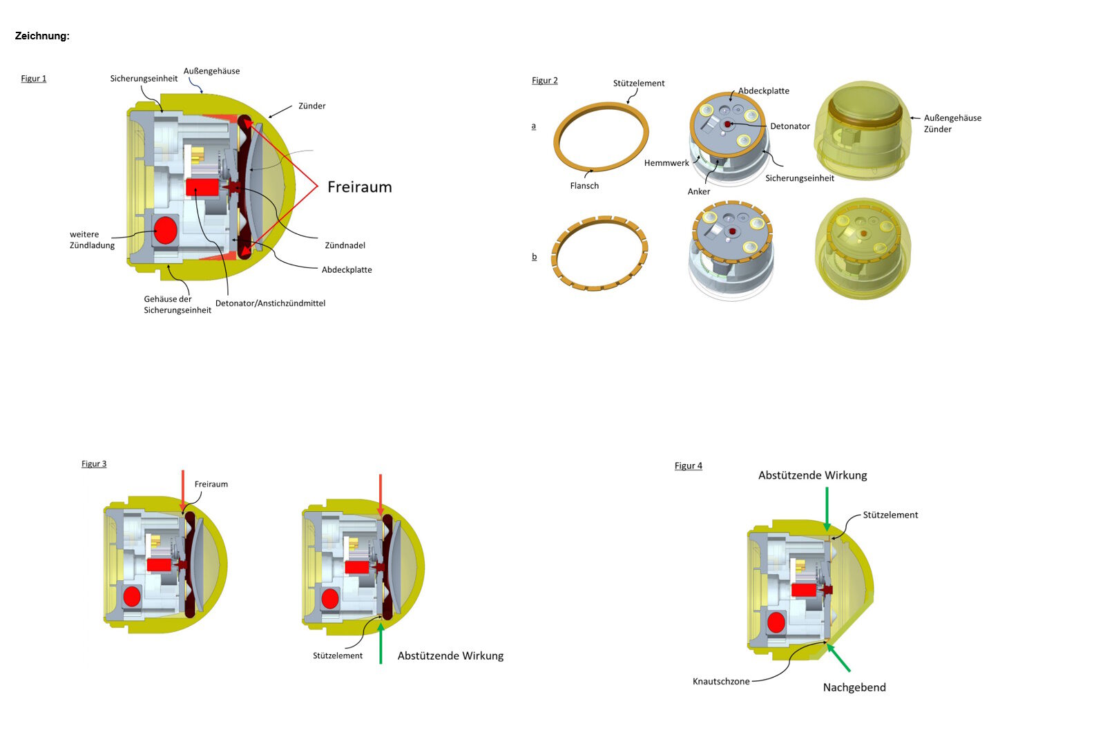
Examples of the proposed solution are shown in the following figures. Figure 1 shows an impact detonator according to the state of the art: The free space between the outer wall of the housing of the fuse unit and the inner wall of the outer housing of the detonator is highlighted in red. The free space is intended to protect the components of the fuse unit from damage if the outer housing is deformed. In the event of a target impact at an angle, the components of the fuse unit can shift in this free space due to their mass. For example, a displacement of the cover plate of the fuse unit at an angle to the longitudinal axis of the detonator can have a negative influence on, for example, the running axles of the escapement mechanism, the bearing seat of the armature wheel in the housing of the fuse unit, toothed segment and armature wheel shaft, pins for the electronic release of the bolt system. The larger the fuse unit is in the longitudinal direction of the detonator, the more serious the deformation of the housing of the fuse unit / displacement of the cover plate will be and the more the functional sequence will be impaired.
Figures 2a and 2b show two variants of a support element. Both support elements are designed in the form of a sleeve with a projecting area in the form of a flange. The flange is designed in such a way that, when the support element is pushed over the cover plate of the fuse unit, it extends laterally to the inner wall of the outer housing of the detonator. Rectangular incisions are also provided in the flange of the support element according to variant b to increase the resilience in the event of an impact at a shallow angle.
In Figure 3, an igniter without a support element is compared to an igniter with a support element in accordance with the proposed solution. If a force is applied to the outer housing of the detonator in the direction of the red arrow during a drop test, the support element exerts a supporting effect, as shown by the green arrow.
Figure 4 clearly demonstrates the supporting effect of the support element in the event of an angular impact. The deformation of the outer housing and the formation of a crumple zone by the flange of the support element is clearly recognisable. In the area of the deformation of the detonator tip, the support gives way, bends against the direction of flight and a crumple zone is formed, which prevents damage and/or displacement of the components of the fuse unit.
Summary
The proposed solution concerns an impact detonator with improved reliability and reduced dud rate compared to prior art detonators. For this purpose, a support element is provided in a free space between a lateral outer wall of the housing of a fuse unit and an inner wall of an outer housing. This support element supports the housing of the fuse unit against the outer housing and thus prevents damage and/or displacement of components of the fuse unit required for reliable operation.