Laser positioning system based on piezoelectric substrates
The present proposed technical solution relates to a device for illuminating an object scene by means of a laser beam comprising a laser module with one or more laser chips arranged on a substrate.

Technical solution proposal B2019-018
Corporate entity: Diehl Defence GmbH & Co. KG
Introduction
The present proposed technical solution relates to a device for illuminating an object scene by means of a laser beam comprising a laser module with one or more laser chips arranged on a substrate.
Problem
In connection with many possible applications of semiconductor lasers, such as in particular quantum cascade lasers (QCL), thin-film lasers, broad-strip lasers, etc., it is necessary to be able to emit a signal in the form of a laser beam by means of a laser module comprising one or more semiconductor lasers, which can be emitted in a specific direction and preferably has the highest possible intensity.
Previous approaches to a solution
In order to be able to emit a laser beam of a laser module in a desired direction, an optical element that can be adjusted via an adjustment system is usually arranged in the beam path of the laser beam of the laser module, which is usually collimated by means of one or more lenses. This can be, for example, a mirror enclosed by an adjustable holder that can be moved manually or electrically via adjusting screws. Another possibility is a micromechanical mirror mounted on an electromechanical resonator, which can be swung out in response to an electric field. These mechanisms have in common that they are large in volume due to the adjustable mounting and are susceptible to vibrations, as they cannot be rigidly installed due to their principle.
The use of piezoelectric actuators is known for adjusting the alignment of optical elements. To obtain a stabilised image of an object on a detector of an optical device, it is proposed in DE 10 2004 020 615 B4 to use a piezoelectric actuator for an optical element of the optical device to keep it in oscillation. EP 1 538 472 B1 describes an imaging device with a per imaging device is described with a micro-optical lens array movable by a piezo actuator for stabilised imaging of an object onto a detector.
Task
The task of the proposed technical solution is to specify a device for illuminating an object scene with a laser beam with a laser module comprising one or more laser chips, the laser beam of which can be influenced in a simple manner, in particular can be directed in different directions and/or influenced with regard to its intensity.
Solution
The proposed technical solution provides for the laser chip or chips to be arranged on a piezoelectric substrate. A laser chip can comprise a single laser or several lasers or emitter structures, i.e. be designed to emit one or more laser beams through corresponding exit facets.
Usually one or more laser chips are soldered onto electrically insulating and thermally well conducting submounts or substrates. To avoid thermal effects and resulting damage to a laser chip, substrates or submounts with high thermal conductivity are used to dissipate the heat generated during laser operation. Since the substrates are electrically insulating, areas on their surface are metallised for the electrical contacting of a laser chip. This benefits from the electrical insulation of the substrate, since no short circuit is generated between different points of the electrical drive circuit of the laser chip and the laser chip together with the substrate or submount can be integrated into an overall system in an electrically neutral manner. For example, well-insulating semiconductors such as beryllium oxide (BeO), silicon carbide (SiC), aluminium nitride (AlN) or diamond, which are only weakly piezoelectric, are used as substrates.
The proposed technical solution is based on the knowledge that methods are now available with which the piezoelectric coefficient of electrically insulating but thermally highly conductive semi-materials, which can be used as substrates or submounts for laser chips, can be increased. The proposed technical solution is also based on the idea that, due to the change in the piezoelectric coefficient of a substrate, the expansion of the substrate can be adjusted by applying an electrical signal and thus the substrate can act as an actuator or control element. The proposed technical solution is further based on the knowledge that, as a result of the change in the expansion of the substrate, one or more laser chips mounted on such a substrate are displaceable with respect to their absolute positions, whereby the position of their respective exit facets is also displaceable.
The proposed technical solution makes it possible to dispense with a separate optical element within the device, which can be aligned with respect to its position, for aligning the path of the laser beam emitted by the laser module. In other words, the proposed technical solution makes it possible to dispense with a positioning system for laser beams or laser beam guidance systems with moving or non-lockable parts that are therefore susceptible to vibrations. As the substrate not only assumes the function of a heat sink, but also that of a positioning system, a reduction in weight and volume is achieved, which is particularly advantageous for devices for which only limited installation space is available or which must not exceed a certain weight. The piezoelectric substrate forms a rigid actuating system which is not susceptible to vibrations and which, due to its electrical controllability and low mechanical inertia, has an increased control speed, e.g. compared to electromechanical actuating systems.
The device expediently has an electronic control unit which is set up to electrically drive the piezoelectric substrate. In particular, the electronic control unit is arranged to cause the substrate to extend parallel and/or orthogonal to the longitudinal axis of the laser chip or chips. Or, in other words, by electrically driving the piezoelectric substrate, the position of the exit facet for the laser beam of a laser of the laser chip can be shifted relative to the position of the exit facet without electrical drive.
Practically, the device additionally comprises at least one lens, preferably a collimating lens, which is located in front of the laser module with respect to the object scene. If an expansion of the substrate parallel to the axis of the laser module is now brought about by the electronic control unit, the focusing of the laser beam passing through the at least one lens can be influenced. The degree of focusing can be adjusted in this way. If an expansion of the substrate orthogonal to the axis of the laser module is brought about by the electronic control unit, the laser beam will pass the at least one lens at a different point compared to the one not in respect of an expansion in the orthogonal axis of the laser module, whereby the direction of propagation of the laser beam is influenced, i.e. a change in the direction of propagation of the laser beam or a beam deflection is brought about.
In a preferred variant of the proposed technical solution, the laser or lasers of a laser chip are quantum cascade lasers, which, like other semiconductor lasers, can be manufactured with very small dimensions, whereby a small-sized laser module and thus an overall small-sized device can be realised, which can also be used in confined spaces.
Preferably, aluminium nitride (AlN) is used as a substrate, which has a high thermal conductivity and is electrically insulating. In this way, the heat generated during operation of the laser chip(s) applied to the AlN substrate can be effectively dissipated and electrical decoupling of the laser chip(s) can be achieved. In a particularly preferred variant, the AlN substrate is doped with scandium, whereby the piezoelectric coefficient of the substrate can be increased and thus its expansion can be adjusted by applying an electrical signal in a further range compared to an undoped substrate.
Design examples
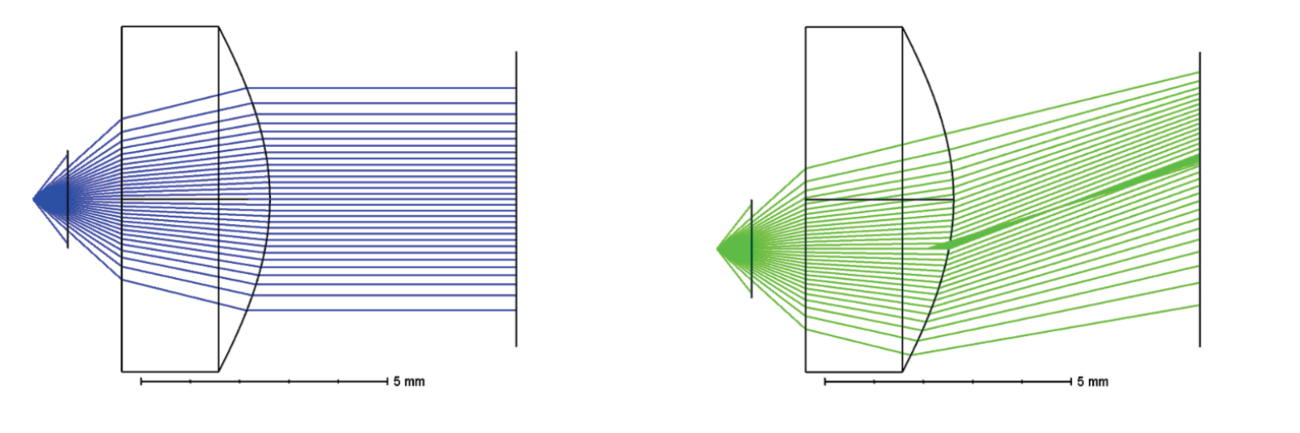
Figure 1 schematically shows the beam path of a laser beam emitted by a laser module of a device for illuminating an object scene, whereby the substrate on which the laser chip of the laser module is arranged is not piezoelectrically controlled. The laser beam passes through a collimating lens, whereby the divergent beam path is converted into a parallel beam path, but there is no beam deflection. Figure 2 shows the same device, but now the laser module is arranged on a piezoelectric substrate which is supplied with a voltage via an electronic control unit. In the present example, the laser module was mounted on an AlN substrate doped with scandium and controlled by means of an electronic control unit, which is not shown, in such a way that the position of the laser chip of the laser module has changed by 1 mm, or more precisely, there has been a displacement of the laser chip by 1 mm downwards in the orthogonal direction with respect to the optical axis of the device. The course of the optical axis of the device is indicated in Figure 2 by the horizontal line running through the centre of the collimating lens. It can be seen that the laser beam of the laser chip passes through the collimating lens at a different position, no longer centrally, due to the displacement of its position with respect to the optical axis. As a result, the divergent beam path is not only collimated, but also undergoes a deflection, in this case by about 20°, and thus no longer runs parallel to the optical axis. Compared to Figure 1, Figure 2 shows that by controlling the piezoelectric substrate, at least one mechanical control element can be compensated for a beam deflection in the further course of the beam and thus a volume reduction of the device can be achieved. In contrast to a device that requires a mechanical actuator, the present device is more robust with regard to external influences, such as vibrations, since the piezoelectric substrate acting as an actuator has no moving parts that are susceptible to vibrations. Although the absolute possible travel of a piezoelectric substrate is smaller compared to a travel achievable by means of mechanical adjusting screws, an optical leverage effect occurs due to the fact that the displacement has a direct effect on the laser chip and the emitted laser beam is not only influenced in the further course of the beam.
For devices for illuminating an object scene by means of a laser beam comprising a laser module with one or more laser chips arranged on a piezoelectric substrate, there are consequently many possible applications, such as for example
- Beam steering of a single laser beam - or multiple laser beams if the laser chip comprises multiple lasers and/or the laser module comprises multiple laser chips - to irradiate a moving target of the object scene (extension of the substrate orthogonal to the laser chip axis)
- Beam steering of a laser beam of a laser module according to the present proposed solution for superimposition with laser beams of a further laser module whose laser chip or laser chips are likewise arranged on a controllable piezoelectric substrate or a non-controllable substrate as heat spreader, for coherent beam superimposition (extension of the substrate orthogonal to the laser chip axis)
- Beam steering of a laser beam inside a resonator with diffractive element for spectral tuning of the laser without moving parts (extension of the substrate orthogonal to the laser chip axis) for illumination of an object scene with a defined wavelength
- Correction of misalignments of the relative positions of one or more optical elements, such as at least one lens, and laser chip during optics assembly of the device (extension of the substrate orthogonal and parallel to the laser chip axis)
- Correction of misalignments of the relative positions of one or more optical elements, such as at least one lens and laser chip during operation of the device due to thermal length changes (temperature compensation) (expansion of the substrate orthogonal and parallel to the laser chip axis).
- Changing the far-field divergence to select wide-angle to narrow-angle illumination of the object scene (extension of the substrate parallel to the laser chip axis).
Extensions of the concept "actuating systems based on piezoelectric materials" are also conceivable with regard to a structured socket of individual light guides or a light guide bundle made of piezoelectric material. In this way, laser beams emitted from a light guide or light guide bundle can also be directed in a desired direction by means of the mount comprising piezoelectric material in the same way as described above in connection with the laser chip and the piezoelectric substrate.