Avionics

-
Control & Display Systems
Multi-Function Displays
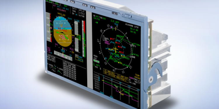
Diehl Aerospace in cooperation with Thales provides Multifunction Displays for all Airbus aircraft types and develops the Display System for the A350 XWB. The Display System allows the presentation of flight and navigation parameters as well as the communication between the crew and the various software applications. The work share of Diehl Aerospace consists of a metal housing with integrated ventilators for the cooling in the case of an emergency, of a Power Supply-I/O Board including an attached AFDX® Module and a graphics processor board. AFDX® is a trademark of Airbus S.A.S.
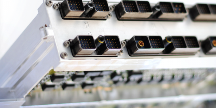
The communication between the six Display Systems that are integrated into the cockpit utilises the integrated AFDX® Modules (100Mb/s full duplex). In addition to that, the Display System includes four CAN bus interfaces (1Mb/s similar to the ones of the A380) and three optical interfaces (glass fiber) for a data transfer of up to 3.1 Gb/s. The screen definition of each display can be adjusted individually. The entire system can be contacted via an ARINC 600 plug on its back. -
Control & Display Systems
Display Management Computers
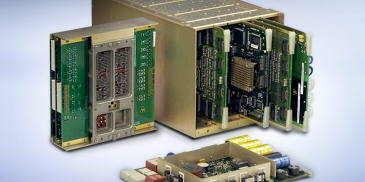
Diehl Aerospace produces the Display Management Computer (DMC) of the A320 Cockpit Display System.
The DMC is a data concentrator, that collects all data from sensors and external sources, consolidates it and sends it to the cockpit displays. -
Control & Display Systems
Symbol Generators
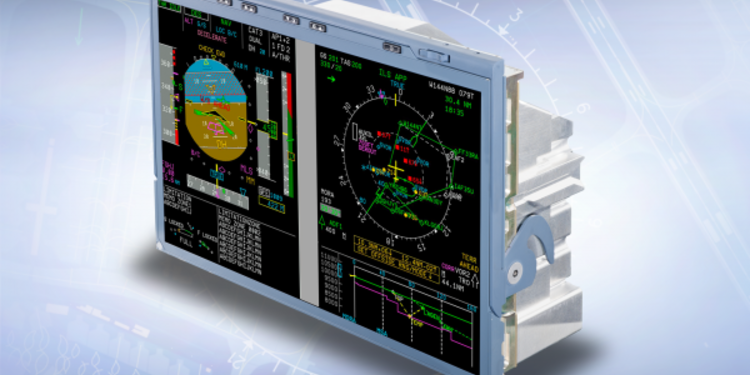
The Diehl Aerospace Center of Excellence for symbol generation develops state-of-the-art technologies for graphic generation and processing. The display systems can be found in the cockpits of many passenger aircraft, such as in the Cockpit and Display System (CDS) and the Onboard Airport Navigation System (OANS) of the Airbus A380.
The Helmet-Mounted Sight Display (HMSD) and Operator ControlPanel (OCP) for the NH90 and Tiger helicopters demonstrate the possible fields of application for these technologies in the military field, too. Recent graphic generation solutions provide abilities to render high definition display resolutions with safety critical flight symbology, moving maps or even synthetic vision as an option. -
Doors and Slides Management
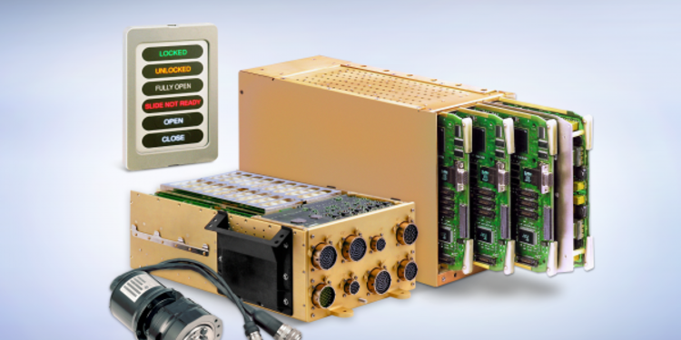
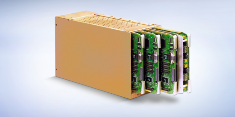
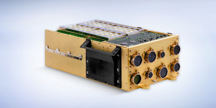
The Doors and Slides Management System (DSMS) is a new electronic system developed by Diehl Aerospace for the Airbus A380. Now, for the first time, it is possible to electronically control and centrally monitor the passenger and freight doors as well as the relevant emergency hatches and slides.
Diehl Aerospace is also developing the Doors and Slides Control System (DSCS) responsible for controlling and monitoring the doors and emergency slides in the A350 XWB. -
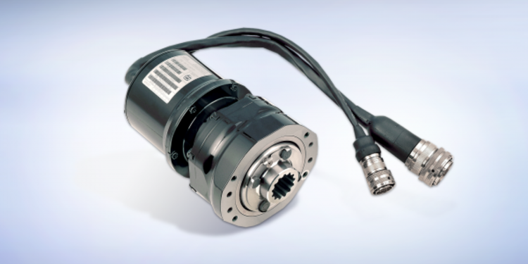
Door Sensors
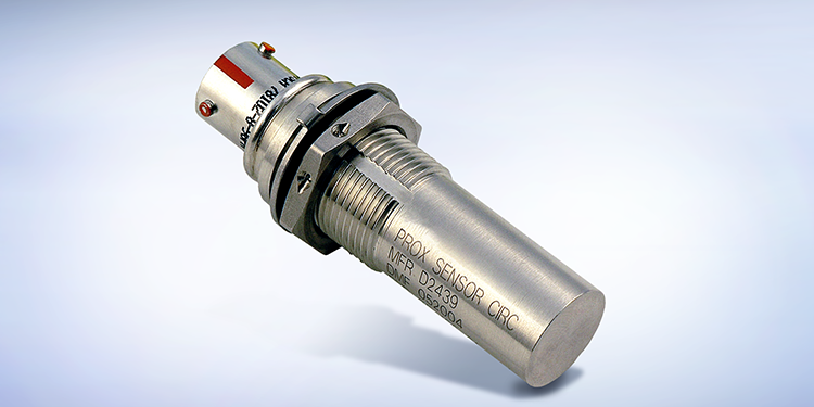
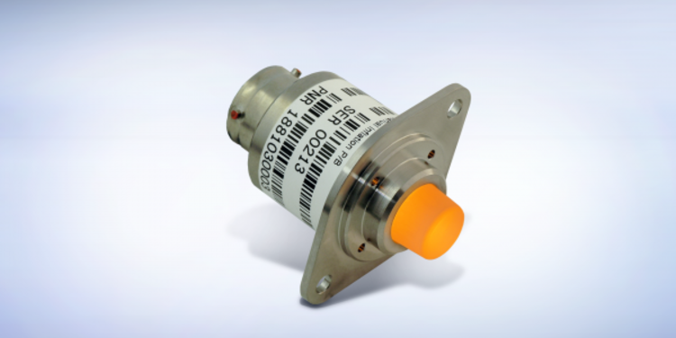
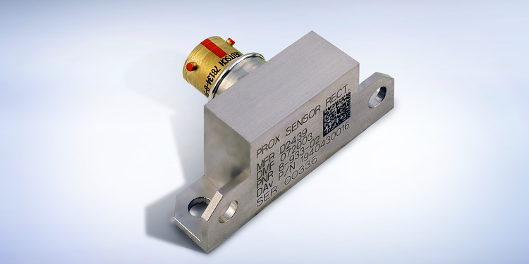
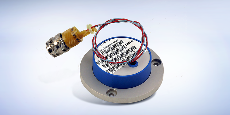
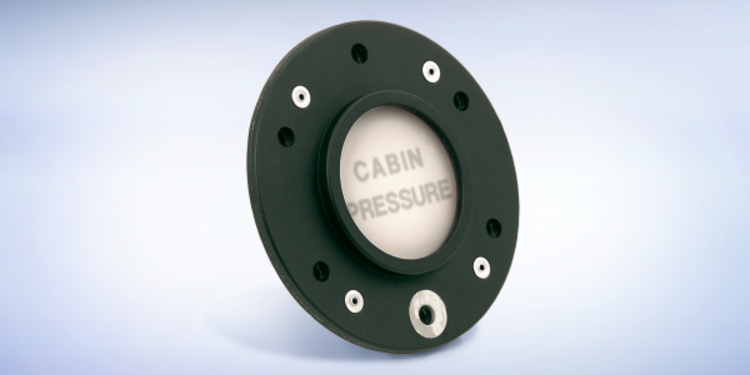
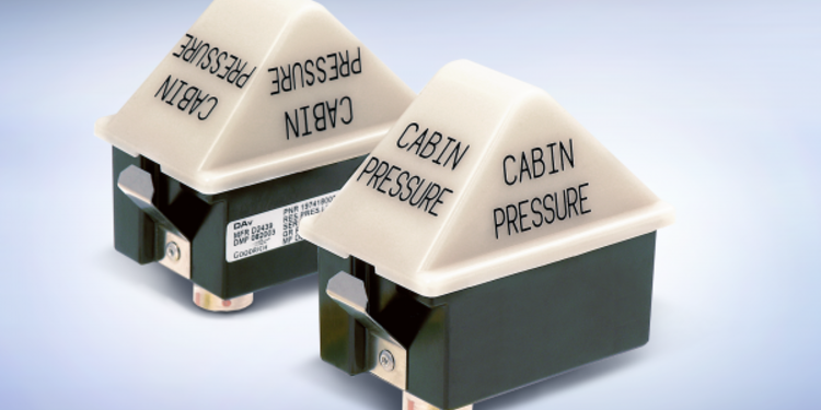
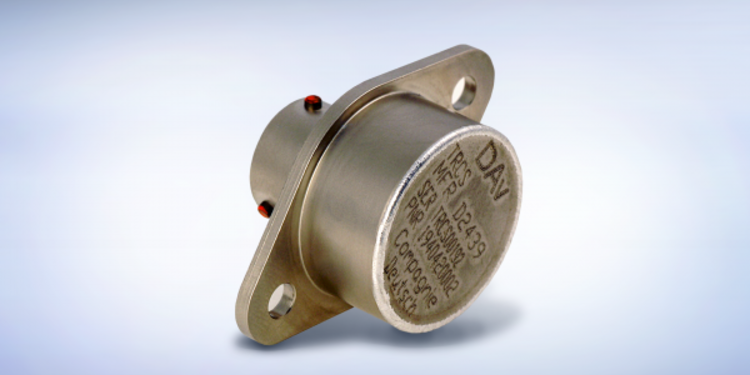
The sensor technology in the doors and slides management systems exists of contactless proximity sensors, contactless reed switches, pitch attitude sensors, and differential pressure switches.
The emphasis in this sensor technology is on contactless inductive sensors. These passive sensors are applied in a round and square design. The sensors themselves consist of a high-precision inductor, which allows – in connection with an especially developed control and evaluation logic (Sensor Interface Module) - a very exact proximity determination between sensor and a defined target. -
Flight Control Unit
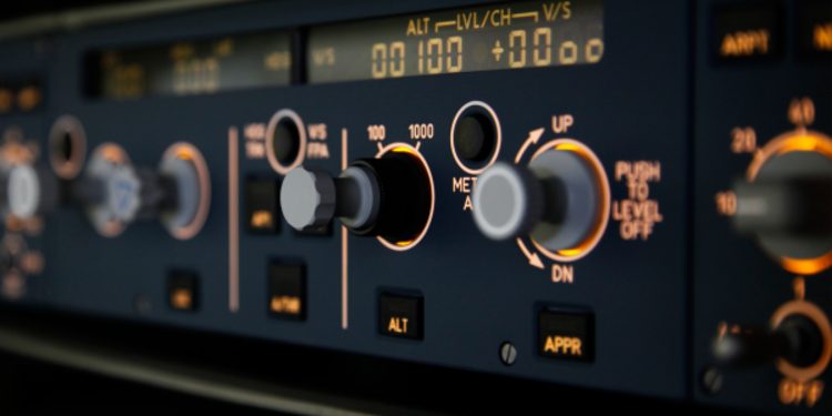
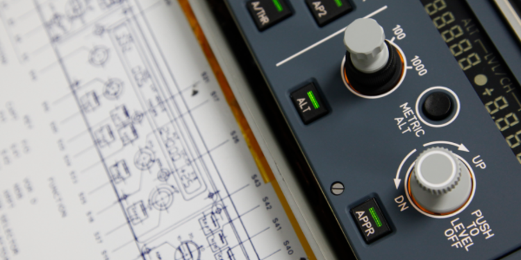
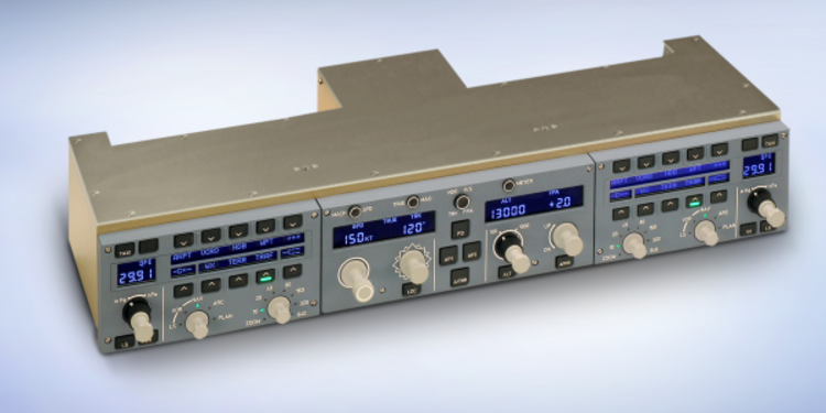
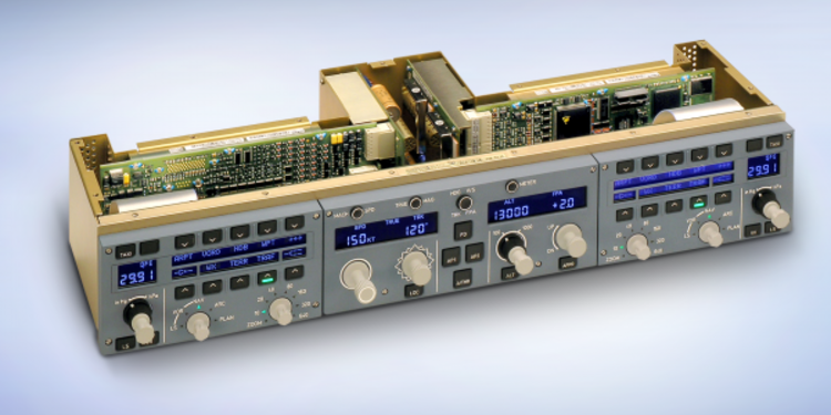
With their Flight Control Unit, Thales and Diehl Aerospace have succeeded in establishing an intelligent interface between the pilot, autopilot, and electronic display system in the cockpit. The FCU is an equipment that contains controls and displays required for: Auto-Flight System, Primary Flight Display configuration including baro setting.
Navigation Display (ND-CP) configuration including: Range and Type of display, Weather information display, Terrain information display, Traffic information display.
The FCU is installed in the glareshield of the Cockpit. -
High Lift Control Systems
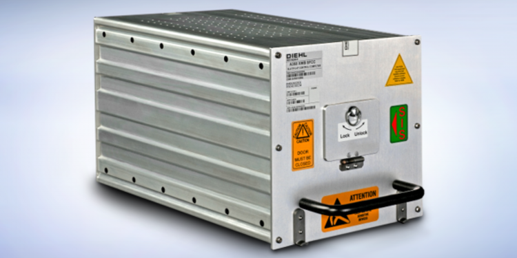
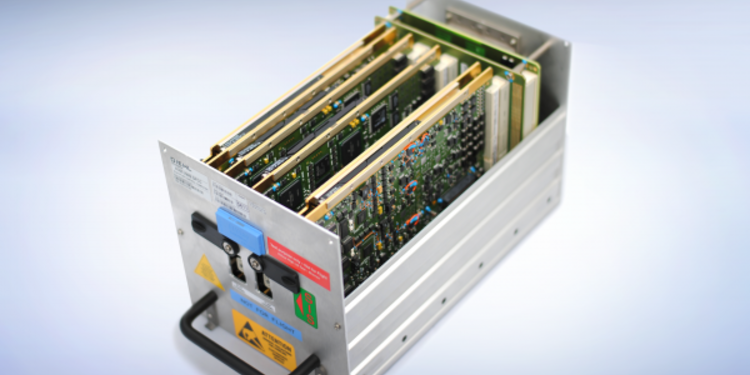
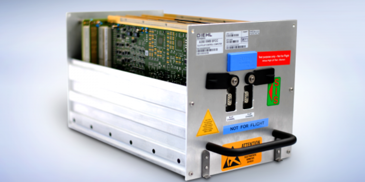
Slat Flap Control Computer
The Slat Flap Control Computer (SFCC) controls and monitors the slats and flaps. This is realised by activation, control and monitoring of the actuators which move the slats and flaps. Each SFCC comprises of one slat and one flap channel.
Both SFCC are able to control the actuators of the flaps and slats respectively, which results in a high availability of the whole system. Highest integrity of the function is assured through failure detection, failure localisation and failure isolationusing a multi duplex (self-checking pair) architecture. -
High Lift Control Systems
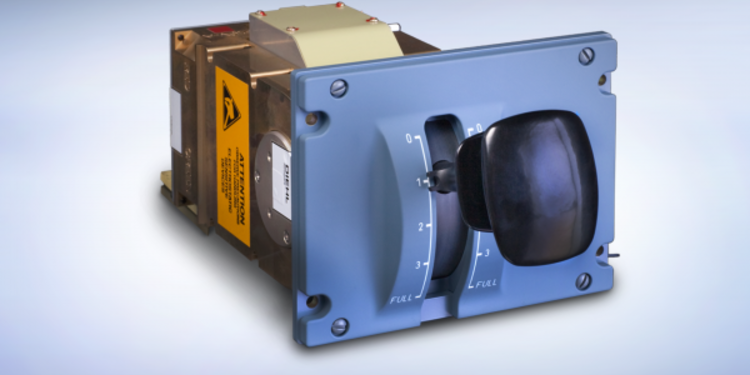
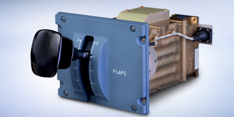
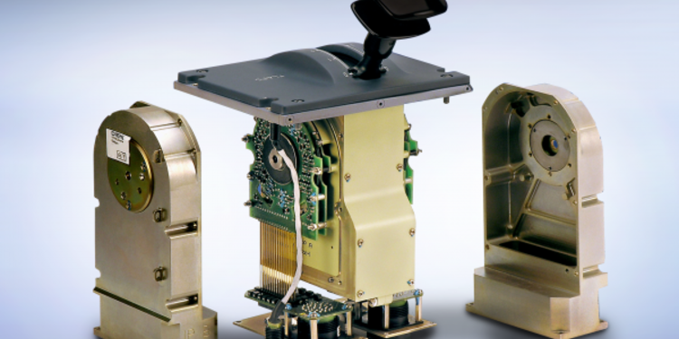
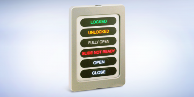
Flaps Lever
The Flaps Lever located in the cockpit is the human-machine-interface of the system. The pilot is using the Flaps Lever to command the high lift system. Two highly accurate Command Sensor Units (CSU) are redundantly sensing the position of the Flaps Lever and convert the mechanical position in electrical signals transmitted to the Slat Flap Control Computers.
-
High Lift Control Systems
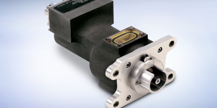
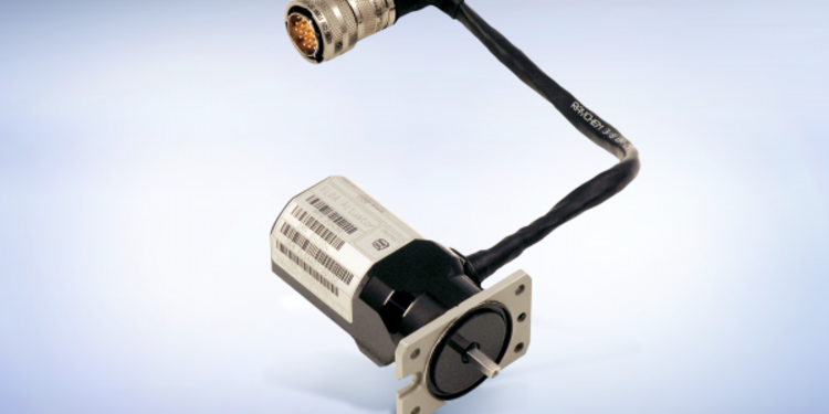
Position Pick-Off Unit
The PPUs, attached to the mechanical system, sense the position of the flaps and slats. PPUs are used to detect discrepancies by comparing the motor, which is the driver of the mechanical system and its outer end. Therefore sensors are allocated on the motor and on the outer end of the wing.
-
High Lift Control Systems
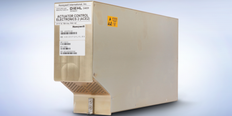
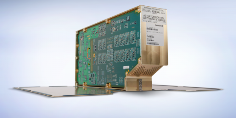
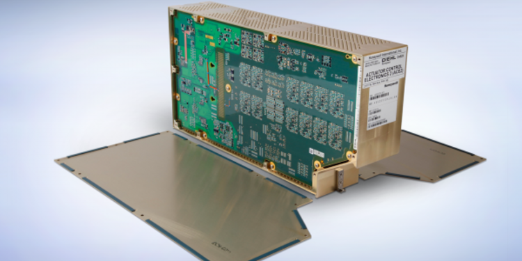
Actuator Control Electronic
The Actuator Control Electronic (ACE) for Honeywell Flight Control Electronic (FCE) of the Boeing 787. The ACE is connected to flight control actuators, associated sensors and acquires signals from the flight control internal and external sensors.
The ACE is designed as self-checking pair and provides the highest data integrity to the flight control application hosted in the Flight Control Modules of the Honeywell FCE. -
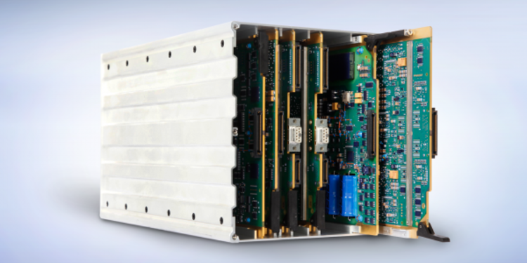
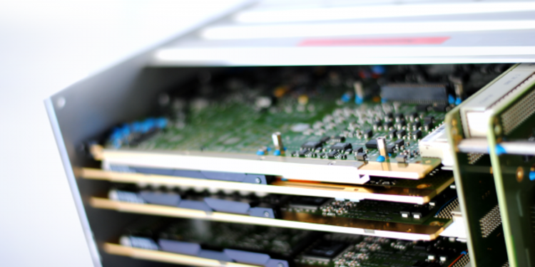
Integrated Modular Avionics

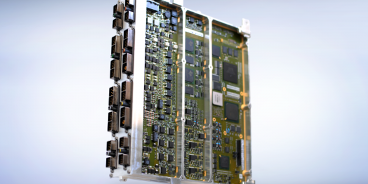
Core Processing Input / Output Module
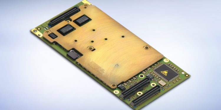
The CPIOM is a high performance computer which provides processing capability to host multiple segregated applications on one computer. A standard ARINC 653 application programmer interface enables clear independence of the application towards the computing device. The flexible core software is fully configurable by the seamless Tool Suite. The CPIOM is connected to the Avionic Full Duplex Switched Ethernet (AFDX®) aircraft bus using Diehl Aerospace's AFDX® End System.
-
Integrated Modular Avionics
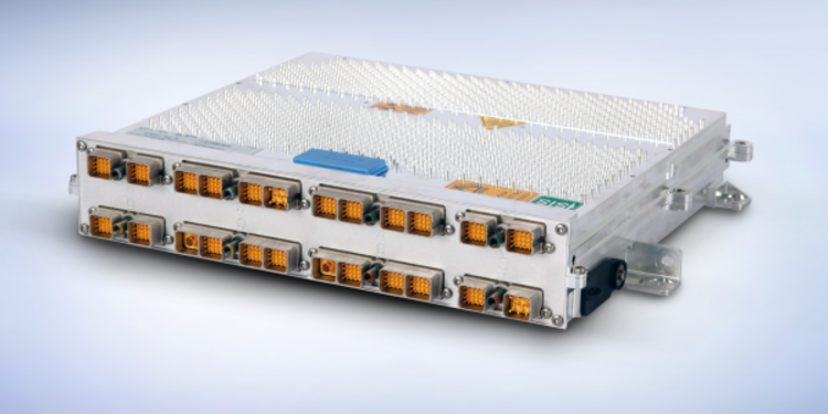
Remote Data Concentrator
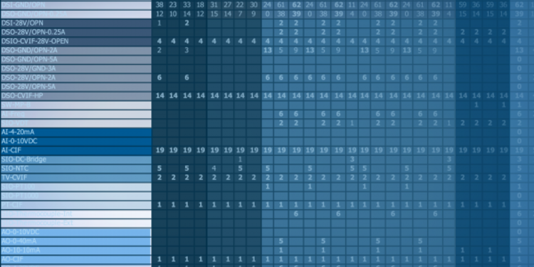
The RDC consists of a high performance I/O computing intelligence including a core software. The interfaces (i.e. inputs, outputs and digital buses) are members of a standardised interface catalogue. Depending on the specific position in the aircraft the RDC selects different pre-defined configurations and adopts the functions accordingly. The RDCs are passively cooled and are located close to actuator and sensors in order to optimise wire weight. Data are collected, converted, monitored and routed to different available outputs. Inputs can be combined and configurable logic operations could be applied to compute new output signals. The RDC acts as a remote input/output intelligence to the centralised core processing computers (CPIOMs).
-
Integrated Modular Avionics
AFDX® End Systems
The AFDX® communication data bus network is a worldwide standard defined in the ARINC 664 documentation. Most of the avionics computers today use this standard for intercommunication. An Avionics Full Duplex Switched Ethernet (AFDX®) End System is available in PMC standard format that can easily be integrated to connect each computer to that network. The AFDX® End System is available also to operate under harsh environmental conditions.
-
Integrated Modular Avionics

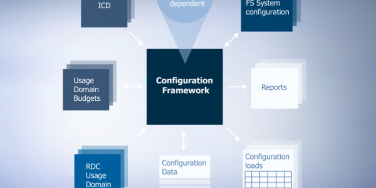
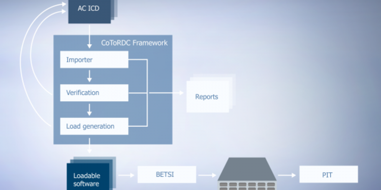
The Integrated Modular Avionics has many users in different roles and with different responsibilities. To support their work tools and services are established to optimise the workload with a high level of automation. The relevant part of the toolchain is certified according to RTCA DO-178B. The following categories of tools are available: Sizing tool to support the platform architecture definition on aircraft level for physical location and assessment regarding relevant parameters e.g. weight, Simulation tool to support early validation of requirements by simulating the functional behaviour of the e.g. RDC, Framework to configure the IMA computers. The configuartion data relates to interfaces, logics and performances, Legacy tools comprising load generation, data loading and platform integration.
-
Auxiliary Power Unit
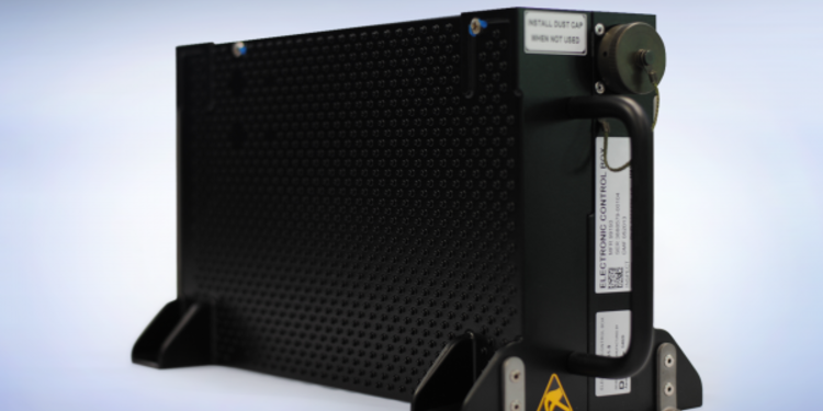
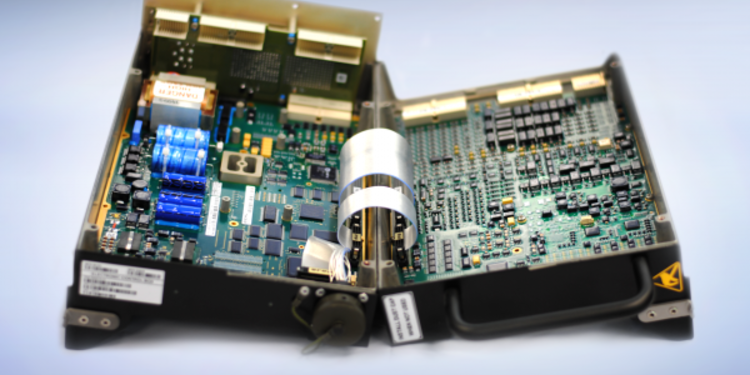
Versatile Electronic Control Box
The abbreviation VECB denotes a universal engine control computer system for auxiliary power units. It controls and monitors the auxiliary power units in the aircraft. The VECB is a versatile system, meaning that the same unit can control different types of single engine families without substantial modifications.
Furthermore, the VECB is equipped with an overspeed protection mechanism, which protects the engine against fatal damages in case of failure. A key advantage of his system is that modifications can be made to other engines with a minimum of effort. Diehl Aerospace is system supplier for the VECB.