Application
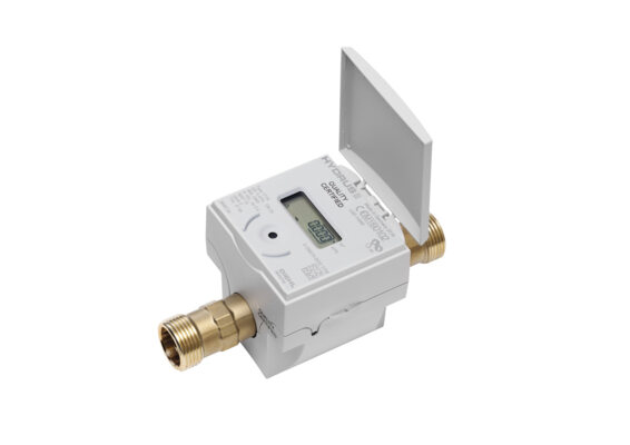
Static ultrasonic water meter for accurate measuring and recording for all applications of water supply.
Features
- Ultrasonic water meter with long-term stability under difficult conditions (no measurement of air and insensitive against sedimentation)
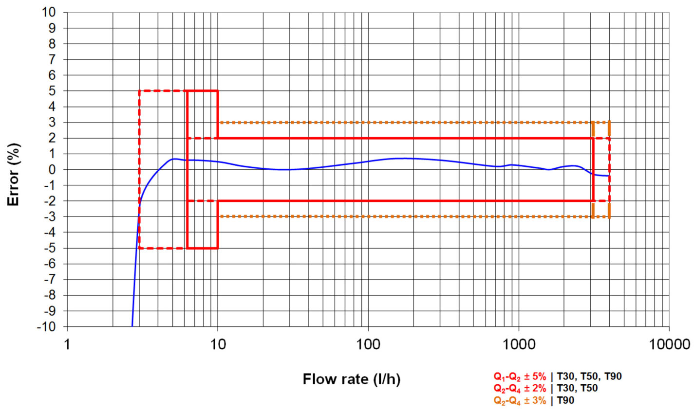
- Higher performance than class D requirements
- Metrological class 2 and dynamic range up to R 400
- Compliant with MID, OIML R49 and EN 14154
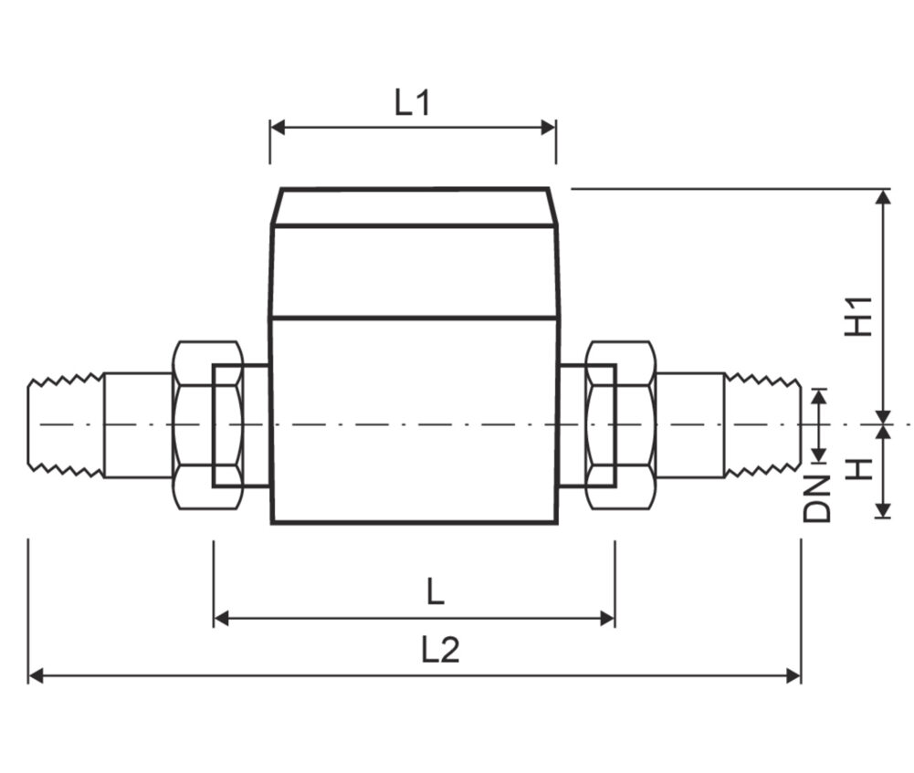
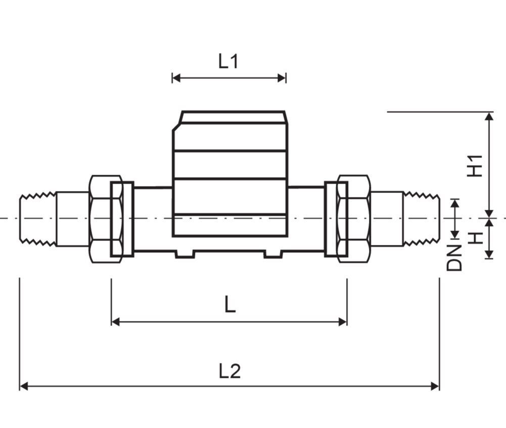
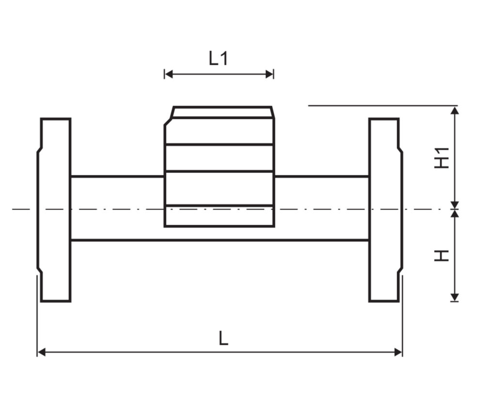
- Mounting in any installation position, no calming sections required
- Housing with thread connection lead-free brass
- IP68 suitable for outdoor installations
- Certified for drinking water (AoC DEU and ACS)
- Wired M-Bus, Radio OMS, Radio/L-Bus and Pulse interface available
- Radio communication based on Open Metering telegram (OMS-Generation 3, Profile A, or OMS-Generation 4, Profile B, selectable)
- Highest data security for AMR communication
- Displaying of error- and alarm codes, including leakage detection
- Battery lifetime up to 16 years
- Data logging capabilities to record up to 1.024 daily values + 32 configurable values (hourly, daily, weekly, monthly) and an annual due date