ULTRASONIC COMPACT ENERGY METER
Application
The ultrasonic compact energy meter can be used for measuring the energy consumption in heating application for billing purposes.
Features
- Approval for ultrasonic meter with dynamic range of 1:100 (qi:qp) in class 2
- Improved power consumption, longer battery lifetime
- High long term stability, tested and verified at independent AGFW test
- Insensitive against dirt
- Extensive readable data memory
- M-Bus communication or 434 MHz integrated radio
-
General
| Application | | | Heating |
| Approval | | | CMC / CPA class 2 |
| Mounting position flow sensor | | | Any position |
| Protection class | | | IP 65 |
| Supply | | | Battery 3.6 VDC, up to 12 years lifetime |
| Temperature sensor type | | | Pt 500 with 2-wire leads; Φ 5.2mm |
| Temperature range medium | | °C | 5 ... 105 |
| Cable length of temperature sensor | | m | 1.5 / 3 / 5 / 10 |
| Volume measuring cycle | | s | 2 |
| Test possibilities | | | Via display, optical test pulses, communication test |
-
Calculator-Basic features
| Environmental class | | | Class C |
| Ambient operating temperature | | °C | 5 ... 55 |
| Ambient storage temperature | | °C | -25 ... +60 (>35°, max. 4 weeks) |
| M-Bus interface | | | According to EN13757-3, GB/T26831, cable length 1.5 m |
| Radio interface | | | Optional, 434 MHz |
| Optical interface | | | ZVEI standard |
| Extensive readable data memory | | | History log; event memory |
-
Display
| Display indication | | | LCD, 8-digits |
| Units | | | kWh (MWh, GJ) |
| Total values | | | 99,999,999 (9,999,999.9 - 999,999.99 - 99,999.999) |
| Values displayed | | | Energy - Power - Volume - Flow rate - Temperature and more |
-
Interface
| M-Bus | | | According to EN 13757-3, GB/T 26831 for data reading and parametrization, auto baud detect (300 and 2400 baud) |
| Radio | | | Open Meter Standard (OMS), according to EN13757-4, GB/T 26831 |
-
Temperature input
| Measuring cycle | T | s | 16 |
| Starting temperature difference | ΔΘ | K | 0.125 |
| Min. temperature difference | ΔΘmin | K | 3 |
| Max. temperature difference | ΔΘmax | K | 102 |
| Temperature range calculator | Θ | °C | 1 ... 130 |
-
Technical data flow sensor
| Nominal flow rate | qp | m3/h | 1.5 | 2.5 | 3.5 | 3.5 | 6 | 6 | 10 |
| Nominal diameter | DN | mm | 15 | 25 | 25 | 32 | 25 | 32 | 40 |
| Overall length | L | mm | 110 | 130 | 260 | 260 | 260 | 260 | 300 |
| Starting flow rate | | l/h | 2.5 | 4 | 7 | 7 | 7 | 7 | 20 |
| Minimum flow rate | qi | l/h | 15 | 25 | 35 | 35 | 60 | 60 | 100 |
| Maximum flow rate | qs | m3/h | 3 | 5 | 7 | 7 | 12 | 12 | 20 |
| Overload flow rate | | m3/h | 4.6 | 6.7 | 18.4 | 18.4 | 18.4 | 18.4 | 24 |
| Operating pressure | PN | bar | 16 | 16 | 16 | 16 | 16 | 16 | 16 |
| Pressure loss at qp | Δp | mbar | 75 | 100 | 44 | 44 | 128 | 128 | 95 |
| Temp. range heating | | °C | 5...105 | 5 ... 105 | 5 ... 105 | 5 ... 105 | 5 ... 105 | 5 ... 105 | 5 ... 105 |
-
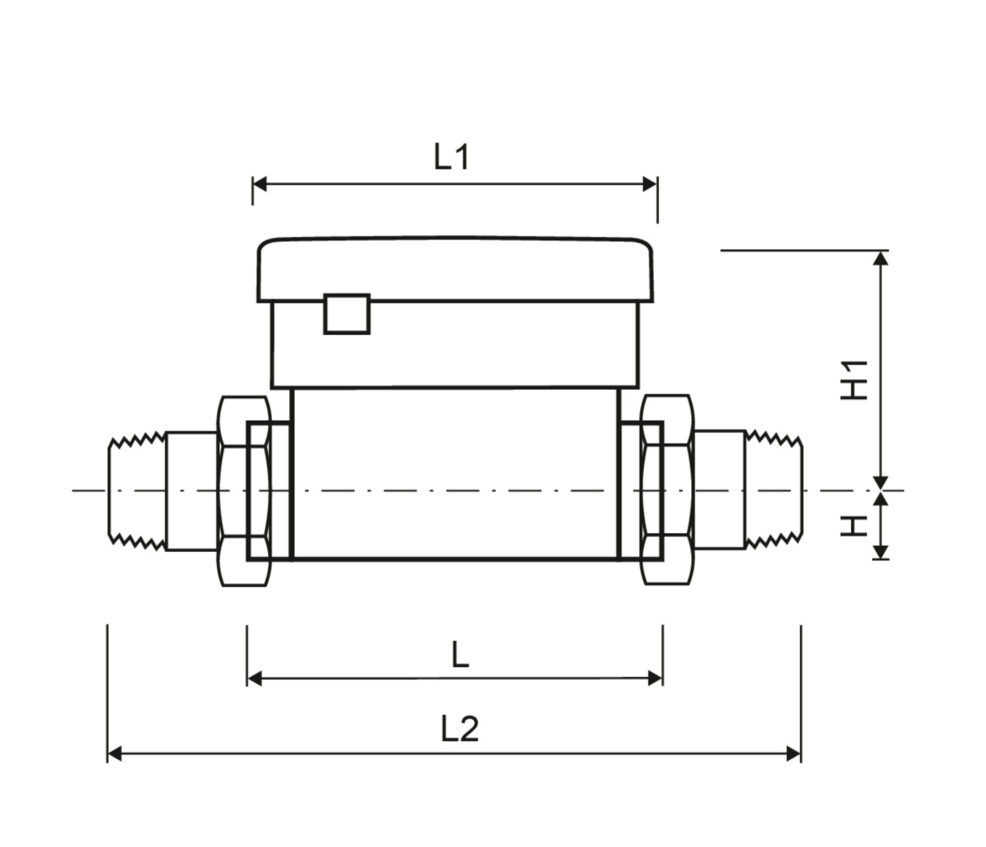
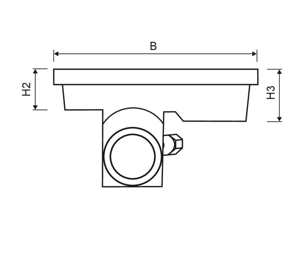
Dimensions thread version
| Nominal flow rate | qp | m3/h | 1.5 | 2.5 | 3.5 | 3.5 | 6 | 6 | 10 |
| Nominal diameter | DN | mm | 15 | 25 | 25 | 32 | 25 | 32 | 40 |
| Overall length | L | mm | 110 | 130 | 260 | 260 | 260 | 260 | 300 |
| Overall length with coupling | L2 | mm | 190 | 250 | 380 | 380 | 380 | 380 | 440 |
| Length of calculator | L1 | mm | 90 | 90 | 90 | 90 | 90 | 90 | 90 |
| Height | H | mm | 14.5 | 23 | 23 | 23 | 23 | 23 | 33 |
| Height | H1 | mm | 55 | 58 | 62.5 | 62.5 | 62.5 | 62.5 | 68 |
| Height of calculator | H2 | mm | 27 | 27 | 27 | 27 | 27 | 27 | 27 |
| Height of calculator | H3 | mm | 40 | 40 | 40 | 40 | 40 | 40 | 40 |
| Width of calculator | B | mm | 135 | 135 | 135 | 135 | 135 | 135 | 135 |
| Connection thread on meter | | Inch | G3/4B | G5/4B | G5/4B | G3/2B | G5/4B | G3/2B | G2B |
| Connection thread of coupling | | Inch | R1/2 | R1 | R1 | R5/4 | R1 | R5/4 | R3/2 |
| Weight | | kg | 0.70 | 0.88 | 1.53 | 1.53 | 1.53 | 1.53 | 3.13 |
-
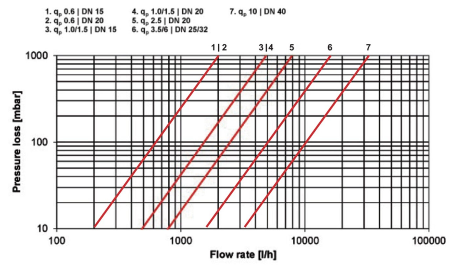
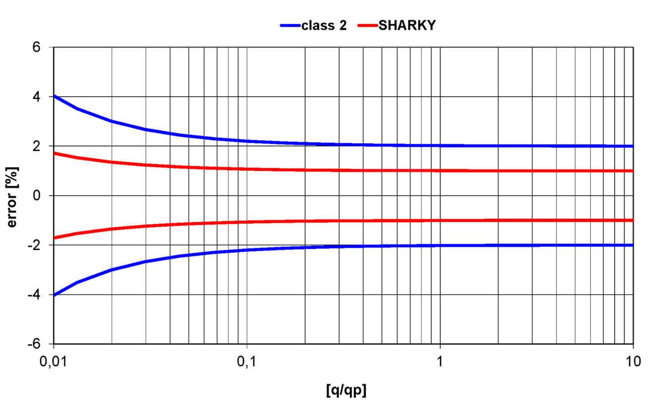
Pressure loss graph/typical errorgraph
-
Pressure loss graph/typical errorgraph
-
Pressure loss graph/typical errorgraph
-
Pressure loss graph/typical errorgraph
-
Pressure loss graph/typical errorgraph
-
Pressure loss graph/typical errorgraph
-
Pressure loss graph/typical errorgraph
-
Pressure loss graph/typical errorgraph