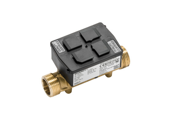
SHARKY FS 473
FLOW SENSOR | ULTRASONIC
Application
The ultrasonic flow sensor can be used for flow measuring in local and district heating / cooling systems.
Features
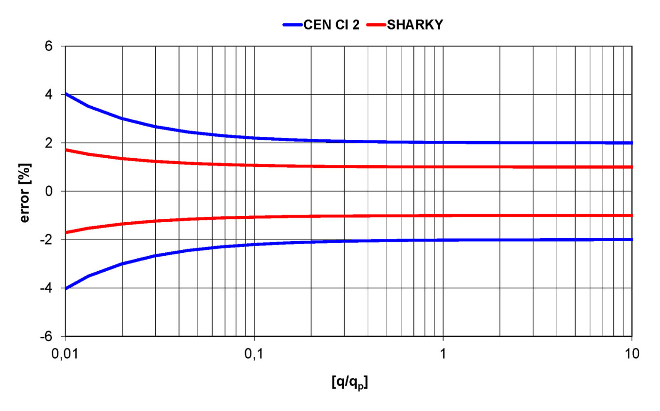
- Dynamic range (DR) of up to 1:250 (qi:qp) in class 2 (depends on meter size), standard 1:100
- Extreme low power consumption --> longer battery lifetime
- Approved according EN 1434 and MID in class 2 and 3 and PTB K 7.2 (cooling)
- High long term stability
- Applicable for different calculators with impulse input
- Continuous time-correct pulses - no pulse packages
- Free selectable impulse values
- The temperature range depending on the applicaton up to 5 ... 150 °C
- Battery or external power supply
- Specific housing for falling and rising pipes
-
General
Application Heating - cooling Approval MID (DE-07-MI004-PTB022) and PTB K 7.2 for cooling (22.76/10.01) Ambient class EN 1434 class C / MID class E2 + M2 Ambient temperature °C 5 ... 55 (<35 °C have a positive lifetime effect) Battery supply 3.0 VDC battery - up to 12 years lifetime External supply 3.0 ... 5.5 VDC Mounting position Any position Protection class Heating: IP 54; heating potted: IP 65; cooling: IP 65 Interfaces Open Collector pulse output1 - output for testing and communication2 Volume pulse value3 10 ml ... 5000 l/pulse (depending on sensor sizes and supply) Cable length of impulse cable 2.4 m (4.9 or 9.9 m optional) Material of the flow sensor body Brass (qp 0.6 ... 100 m³/h), spheroidal cast iron (qp 15 ... 100 m³/h) 1 The pulse output can be choosen without galvanic isolation (standard) or with galvanic isolation (only with battery supply). The flow sensor has by default a 4-wire impulse cable.
2 The flow sensor can either emit a high resolution test pulse (standard) or communicate via the same output. By using an adapter the flow sensor can be read via the HYDRO-SET software.
3 The pulse duration is between 1 and 250 ms. It depends on the pulse value and on the nominal flow rate qp.
Standard pulse values: 1, 2.5, 10, 25, 100, 250 l/pulse -
Reach
Information pursuant to Article 33 (1) of Regulation (EC) No 1907/2006 of the European Parliament and of the Council of 18 December 2006:
This product series contains components with the following substances in a concentration of more than 0.1% weight by weight (w/w):
- Lead (CAS no.: 7439-92-1)
- Lead titanium zirconium oxide (CAS no.: 12626-81-2)
- 1,2-dimethoxyethane (CAS no.: 110-71-4) -
Temperature range
Temperature range heating - battery supplied °C 5 ... 90 / 5 ... 1051 Temperature range heating - external supplied °C 5 ... 105 / 130 / 150 (depends on meter size and material) Temperature range cooling - battery supplied / external supplied °C 5 ... 50 / 5 ... 90 1 Only in rising or falling pipes or tilted horizontal installation -
Technical data
Nominal flow rate qp m3/h 0.6 0.6 0.6 1.5 1.5 1.5 2.5 2.5 3.5 3.5 3.5 3.5 3.5 6 6 6 6 6 6 10 10 15 25 40 60 100 Nominal diameter DN mm 15 20 20 15 20 20 20 20 25 25 25 32 32 25 25 25 32 32 40 40 40 50 65 80 100 100 Overall length L mm 110 130 190 110 130 190 130 190 135 150 260 150 260 135 150 260 150 260 150 200 300 270 300 300 360 360 Starting flow rate l/h 1 1 1 2.5 2.5 2.5 4 4 10 10 10 10 10 10 10 10 10 10 10 20 20 40 50 80 120 120 Minimum flow rate (DR 1:250) qi l/h 6 6 6 6 6 6 10 10 - - - - - 24 24 24 24 24 - 401 401 601 1001 1601 2401 4001 Minimum flow rate (DR 1:100) qi l/h 6 6 6 15 15 15 25 25 35 35 35 35 35 60 60 60 60 60 60 100 100 150 250 400 600/12002 1000/12002 Minimum flow rate (up side down installation) qi l/h 6 6 6 6 6 6 10 10 35 35 35 35 35 24 24 24 24 24 100 100 150 250 400 1200 1200 Maximum flow rate qs m³/h 1.2 1.2 1.2 3 3 3 5 5 7 7 7 7 7 12 12 12 12 12 12 20 20 30 50 80 120 120 Overload flow rate m³/h 2.5 2.5 2.5 4.6 4.6 4.6 6.7 6.7 18.4 18.4 18.4 18.4 18.4 18.4 18.4 18.4 18.4 18.4 18.4 24 24 36 60 90 132 132 Pressure loss at qp Δp mbar 95 85 85 120 75 75 100 100 44 44 44 44 44 128 128 128 128 128 190 140 140 140 75 80 75 210 Temp. range heating - brass body °C 5 ... 130 5 ... 130 5 ... 130 5 ... 130 5 ... 130 5 ... 130 5 ... 130 5 ... 130 5 ... 150 5 ... 150 5 ... 150 5 ... 150 5 ... 150 5 ... 150 5 ... 150 5 ... 150 5 ... 150 5 ... 150 5 ... 150 5 ... 150 5 ... 150 5 ... 150 5 ... 150 5 ... 150 5 ... 150 5 ... 150 Temp. range heating - spheroidal cast iron body / brass PN 40 °C - - - - - - - - - - - - - - - - - - - - - 5 ... 105 5 ... 105 5 ... 105 5 ... 105 5 ... 105 kv value (qp² (m³/h) = kv² x Δp (bar)) 1.95 2.06 2.06 4.33 5.48 5.48 7.91 7.91 16.69 16.69 16.69 16.69 16.69 16.77 16.77 16.77 16.77 16.77 13.76 26.73 26.73 40.09 91.29 141.42 219.09 218.22 1 Valid for horizontal installation only
2 Up side down installation -
Dimensions thread version
Nominal flow rate qp m3/h 0.6 0.6 0.6 1.5 1.5 1.5 2.5 2.5 3.5 3.5 3.5 3.5 3.5 6 6 6 6 6 6 10 10 15 25 40 60 100 Nominal diameter DN mm 15 20 20 15 20 20 20 20 25 25 25 32 32 25 25 25 32 32 40 40 40 50 65 80 100 100 Overall length L mm 110 130 190 110 130 190 130 190 135 150 260 150 260 135 150 260 150 260 150 200 300 270 300 300 360 360 Overall length with coupling L2 mm 190 230 - 190 230 - 230 - 255 270 380 270 380 255 270 380 270 380 - 340 440 - - - - - Height H mm 14.5 18 18 14.5 18 18 18 18 23 23 23 23 23 23 23 23 23 23 33 33 33 - - - - - Height H1 mm 54.5 56.5 56.5 54.5 56.5 56.5 56.5 56.5 61 61 61 61 61 61 61 61 61 61 61 66.5 66.5 - - - - - Length of electronic L1 mm 90 90 90 90 90 90 90 90 90 90 90 90 90 90 90 90 90 90 90 90 90 - - - - - Width of electronic B mm 65.5 65.5 65.5 65.5 65.5 65.5 65.5 65.5 65.5 65.5 65.5 65.5 65.5 65.5 65.5 65.5 65.5 65.5 65.5 65.5 65.5 - - - - - Connection thread on meter Inch G¾B G1B G1B G¾B G1B G1B G1B G1B G1¼B G1¼B G1¼B G1½B G1½ B G1¼B G1¼B G1¼B G1½B G1½ B G2B G2B G2B - - - - - Connection thread of coupling Inch R½ R¾ R¾ R½ R¾ R¾ R¾ R¾ R1 R1 R1 R1¼ R1¼ R1 R1 R1 R1¼ R1¼ R1½ R1½ R1½ - - - - - Operating pressure PN bar 16/25 16/25 16/25 16/25 16/25 16/25 16/25 16/25 16/25 16/25 16/25 16/25 16/25 16/25 16/25 16/25 16/25 16/25 16/25 16/25 16/25 - - - - - Weight kg 0.6 0.61 0.63 0.6 0.61 0.63 0.61 0.63 0.88 0.93 1.35 1.08 1.35 0.88 0.93 1.35 1.08 1.35 1.52 2.4 2.6 - - - - - -
Dimensions flange version
Nominal flow rate qp m3/h 0.6 0.6 0.6 1.5 1.5 1.5 2.5 2.5 3.5 3.5 3.5 3.5 3.5 6 6 6 6 6 6 10 10 15 25 40 60 100 Nominal diameter DN mm 15 20 20 15 20 20 20 20 25 25 25 32 32 25 25 25 32 32 40 40 40 50 65 80 100 100 Overall length L mm 110 130 190 110 130 190 130 190 135 150 260 150 260 135 150 260 150 260 150 200 300 270 300 300 360 360 Height H mm - - 47.5 - - 47.5 - 47.5 - - 50 - 62.5 - - 50 - 62.5 - - 69 73.5 85 92.5 108 108 Height H1 mm - - 56.5 - - 56.5 - 56.5 - - 61 - 61 - - 61 - 61 - - 66.5 71.5 79 86.5 96.5 95.5 Length of electronic L1 mm - - 90 - - 90 - 90 - - 90 - 90 - - 90 - 90 - - 90 90 90 90 90 90 Width of electronic B mm - - 65.5 - - 65.5 - 65.5 - - 65.5 - 65.5 - - 65.5 - 65.5 - - 65.5 65.5 65.5 65.5 65.5 65.5 Flange dimension F mm - - 95 - - 95 - 95 - - 100 - 125 - - 100 - 125 - - 138 147 170 185 216 216 Flange diameter D mm - - 105 - - 105 - 105 - - 114 - 139 - - 114 - 139 - - 148 163 184 200 235 235 Hole circle diameter K mm - - 75 - - 75 - 75 - - 85 - 100 - - 85 - 100 - - 110 125 145 160 1801 / 190 1801 / 190 Screwhole diameter D1 mm - - 14 - - 14 - 14 - - 14 - 18 - - 14 - 18 - - 18 19 19 19 191 / 22 191 / 22 Operating pressure PN bar - - 16/25 - - 16/25/403 - 16/25/403 - - 16/25/403 - 16/25/403 - - 16/25/403 - 16/25/403 - - 16/25/403 16/25/403 16/25 16/25/403 16/25 16/25 Number of screwholes pcs - - 4 - - 4 - 4 - - 4 - 4 - - 4 - 4 - - 4 4 8 8 8 8 Weight brass body2 kg - - 2.7 - - 2.7 - 2.7 - - 3.35 - 4.65 - - 3.35 - 4.65 - - 6.6 7.45 9.45 11.1 16.9 16.9 Weight spheroidal cast iron body2 kg - - - - - - - - - - - - - - - - - - - - - 6.31 8.08 10.01 15.76 15.75 1 Values for PN 16 housing
2 Meter with battery and 2.4 m cable length of the pulse cable
3 Only up to 105 °C -
Pressure loss graph / typical error graph