SIGNAL CONVERTER 520.11

ELECTRONIC ACCESSORY | DISPLAY AND CONTROL DEVICES

Application

The spectrum of applications primarily covers the transmission of instantaneous values and provides the basis for the display and/or recording of flow rates in pipes. The current output is also used for various control and monitoring tasks.

Features

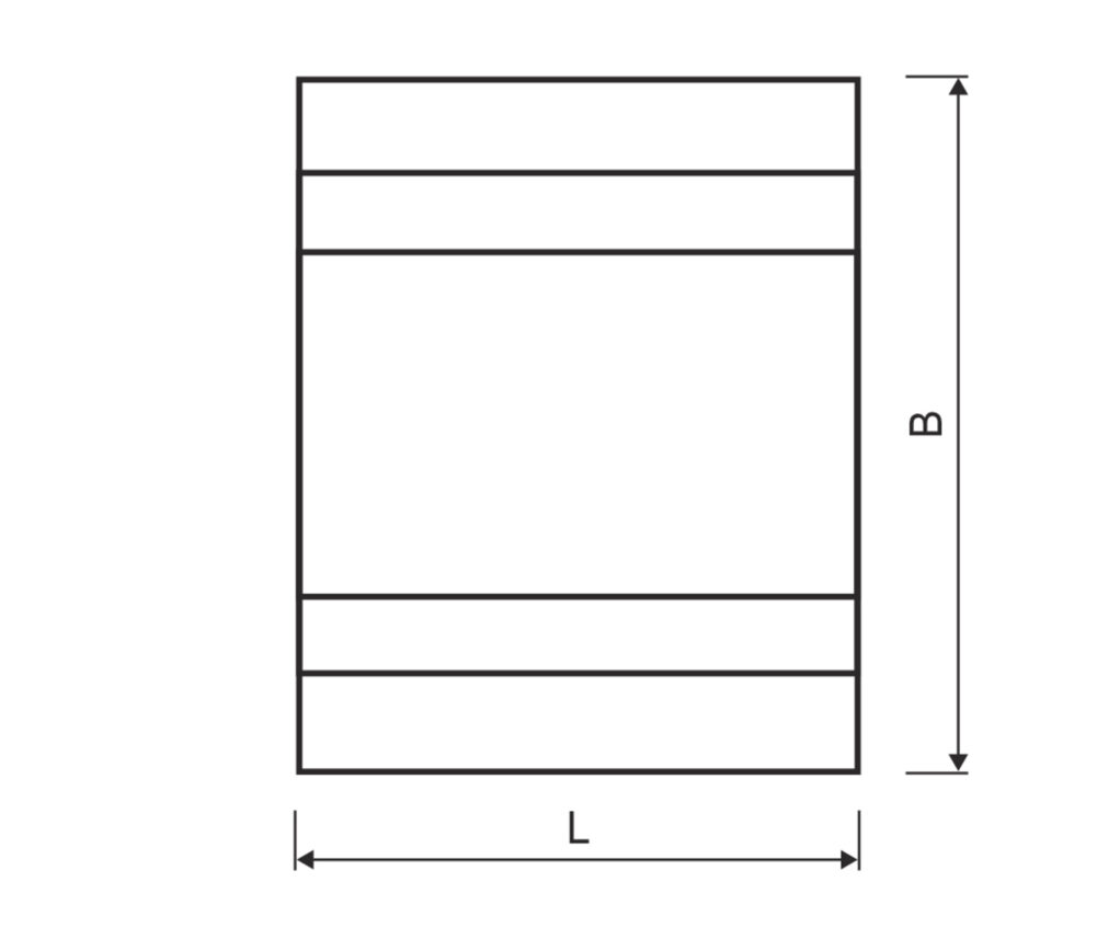
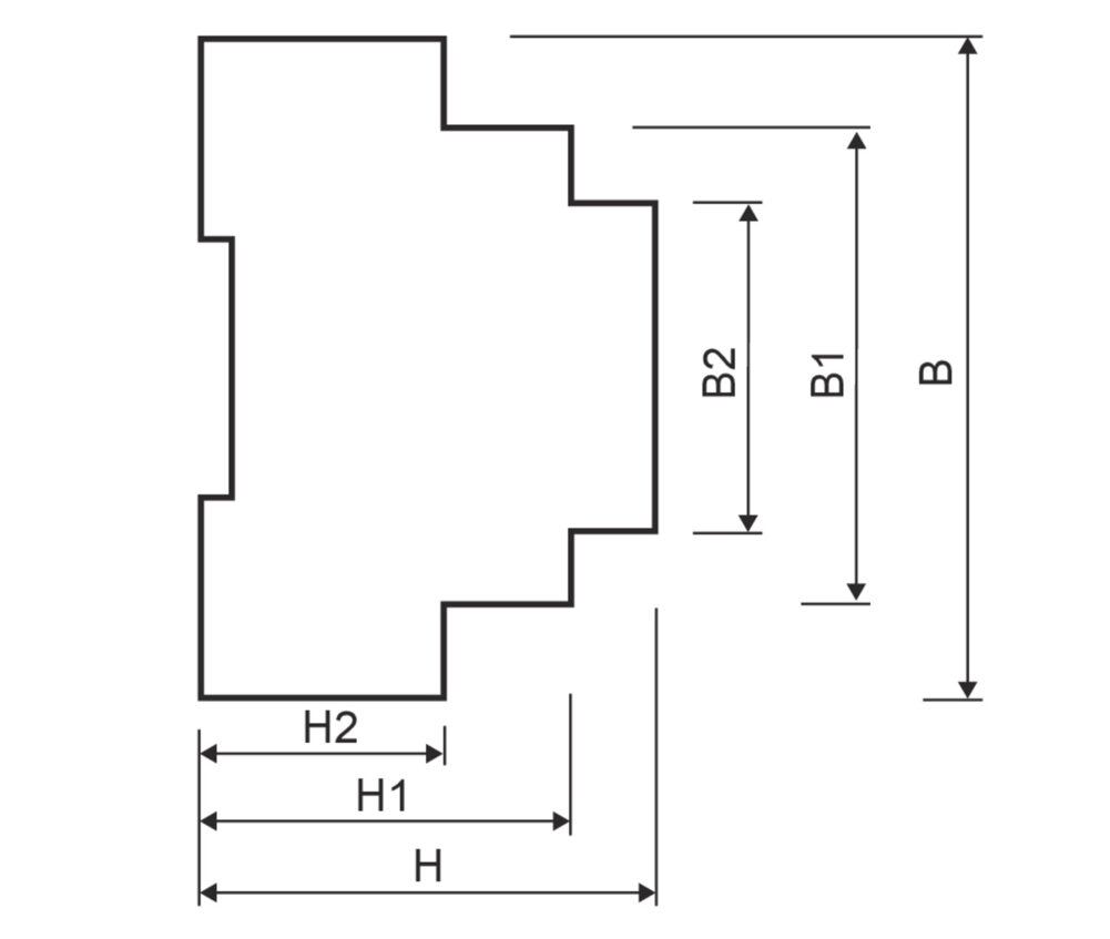
  • Designed as snap-on housing for mounting rail
  • 2-channel control options for compound meter: infrared reflex pulse transmitter (571), two-wire proximity switch to DIN 19234 (NAMUR) (572, 573) self-optimizing level, electronic counter module, mechanical compact energy meter RAY
  • Front-panel programming buttons for setting menu controlled functions
  • Freely programmable input pulse values
  • Filtered output signal 0/4 mA ... 20 mA and 0/2 V ... 10 V
  • 1 floating output (make contact, open collector)
  • Electrically isolated measuring and supply circuits
  • Selftest, self-monitoring
  • LC display for flow rate (m3/h or l/s); min./max. flow rate; meter reading; menu guidance
  • M-Bus interface (option)
  • Function

    The microprocessor-controlled LCD universal signal converter converts the pulses from the volume measuring components in the water meters (main meters and submeters) to a dc current proportional to the flow rate (digital-analogue converter). The current amplitude is proportional to the instantaneous flow rate.
    The converter is also used for converting high-resolution pulses to decadic pulses (e.g. m3). The signal converter 520.11 is programmed via touch controls on the front panel.

  • Technical data
    Supply voltage20 ... 250 V AC / DC, approx. 100 mA ... 10 mA
    Linearity%< 0.4
    Temperature drift%< 0.5 (0 ... 55 °C)
    Storage temperature°C-20 ... +70
    Operating temperature°C-10 ... +55
    InputsInfrared reflex light barrier (571), Infrared light barrier with amplifier (PV-14), Proximity switch (NAMUR) to DIN 19625/EN 50227 (572, 573), electronic counter module, RAY
    Input frequency rangeHz0 ... 0.1 to 0 ... 99.9
    Output currentmA0 (4) ... 20 (max. load 650 Ω)
    Output voltageV0 (2) ... 10 (min. load 3 kΩ)
    Pulse outputOptocoupler bipolar FET (make), max. 230 V AC / 100 mA
    Pulse valueFreely adjustable
    Display indicationLCD, 2-line
    Values displayedCurrent flow rate, current meter reading, min./max. flow rates
    Setting / programmingVia touch controls / menu-controlled entry of programming data
    Housing - typeSnap-on housing
    Housing - fixingMounting rail to DIN 46277
    Protection classIP 30
    WeightgApprox. 400
    EMC - interference immunityEN 50081-1
    EMC - noise emissionEN 50082-2
  • Note

    The use of overvoltage protectors is recommended if long cables are necessary for connecting the measuring sensor to the signal converter or the converter to the display unit.

  • Dimensions
    LengthLmm72
    WidthBmm91
    WidthB1mm65
    WidthB2mm46
    HeightHmm62
    HeightH1mm51
    HeightH2mm33
  • Order references
    TypeStandard
    Article number520 000 18
  • Connections

  • Connection of sensors

  • Connection of sensors / meters